
01 / Project overview
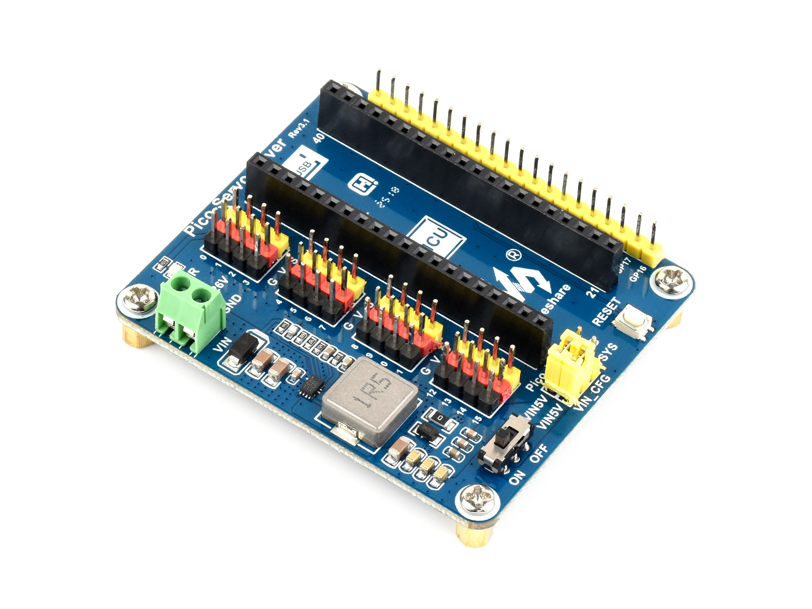
This build uses two channels of the Waveshare Pico Servo Driver for a small pan-and-tilt mechanism. Start with the servos unloaded and establish their usable travel before fitting the bracket. The module is a Pico GPIO/PWM design; do not substitute the setup for a different PCA9685-based HAT.
02 / Materials & software
| Item | What to check |
|---|---|
| Pico Servo Driver and Pico | Use the module’s matching official example. |
| Two compatible small servos | Check their rated voltage and travel. |
| Lightweight pan-and-tilt bracket | Avoid a heavy camera during first tests. |
| Suitable servo power supply | Size it for the motors and module; follow the manual. |
03 / Connections & first setup
Disconnect power while fitting headers and servo plugs. Confirm signal, supply, and ground orientation for every connector. Follow the module’s power-input arrangement and never expect a Pico GPIO or its 3.3V rail to supply motor current.
04 / Build the project
- Test one unloaded servo
Run the official example on one channel with the horn removed or safely unloaded. Move only within a conservative range. Listen for strain and stop if the mechanism reaches a hard stop.
- Find the center
Command the documented center position and fit the horn to suit the bracket. Mechanical centering is easier before the second axis is attached. Write down the channel and mounting orientation.
- Set usable limits
Approach each end slowly and choose software limits inside the mechanical limits. Record them separately for pan and tilt. A generic zero-to-180-degree assumption is not a substitute for checking the actual servo and linkage.
- Add gradual motion
Move toward a target in small steps or with a time-based ramp. Keep the control loop responsive to a stop command. Avoid commanding both axes through their full range while the bracket is being held by hand.
- Fit a light payload
Secure the rig on the bench and repeat the test with a lightweight pointer or dummy load. Check cable slack through the full allowed range. Add the intended payload only after the mechanism remains stable.
Motion rule — pseudocode
target = clamp(requested_angle, measured_min, measured_max)
next_angle = approach(current_angle, target, allowed_step)
write_servo(next_angle)
if stop_requested: stop_scheduling_new_moves()
05 / Check the result
| Check | Expected behavior |
|---|---|
| Neutral position | Each axis starts inside its safe mechanical range. |
| Limit request | Out-of-range commands are constrained. |
| Combined motion | No cable catches and no axis strains at its limit. |
Troubleshooting. Jitter can come from power, grounding, a strained linkage, or incorrect pulse settings. Test one unloaded servo before changing both the power system and code. A stalled motor is a mechanical fault to resolve, not a reason to widen the software limits.
06 / Sources & build notes
Prepared by PineMux from the official sources above. These are editorial build instructions; this project has not been bench-tested by PineMux. The cover shows reference hardware or a source project; image credit is provided above. Use the manufacturer’s revision-specific diagrams for exact wiring.