
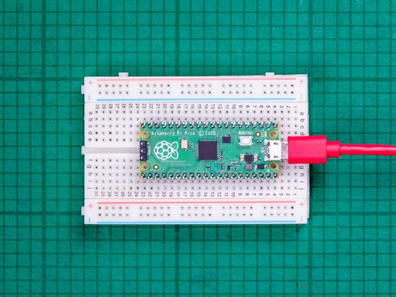
01 / Project overview
The Pico’s internal sensor is useful for exploring ADC readings and the relationship between electrical measurements and calculated values. The official MicroPython example uses ADC channel 4. It measures the chip’s temperature, which can differ from the surrounding air.
02 / Materials & software
| Item | What to check |
|---|---|
| RP2040 Raspberry Pi Pico | Use an RP2040 Pico for this example. |
| USB data cable | Keep the same supply for comparisons. |
| MicroPython firmware | Install the board-appropriate build. |
| Serial editor | Use Thonny or another compatible REPL tool. |
03 / Connections & first setup
No external sensor wiring is required. Leave unused pins disconnected for the first exercise. Save the exact firmware version with your notes because the experiment is easier to repeat when the software and supply conditions remain consistent.
04 / Build the project
- Confirm the REPL
Install MicroPython and print a short message. Check that the device reconnects after reset. Keep the first logger interactive so an error is visible instead of being hidden in an automatic startup file.
- Run the official ADC example
Use the linked Raspberry Pi example to obtain voltage and temperature. Record both values. Retaining the raw measurement makes it possible to revisit a conversion assumption later.
- Choose a sampling interval
Sample at a steady, modest interval and print a header once. Include elapsed time if no real-time clock is available. Do not label elapsed seconds as UTC or local clock time.
- Capture a baseline
Leave the board in one location and collect several minutes of readings. Note changes in USB supply, enclosure, or workload. Compare trends rather than claiming a calibrated absolute air temperature.
- Export and inspect
Save the serial output as a CSV file on the computer. Check for duplicate headers, missing rows, and resets. Only after that should you add persistent storage or a display.
Suggested output
elapsed_s,adc_raw,sensor_voltage_v,chip_temperature_c
0,example_raw,example_voltage,example_temperature
05 / Check the result
| Check | Expected behavior |
|---|---|
| Time sequence | Elapsed time increases at the intended interval. |
| Reset | A new run can be identified in the captured data. |
| Interpretation | The chart is labeled chip temperature. |
Troubleshooting. A believable number is not proof of calibration. Supply and ADC assumptions affect the conversion, while board heating affects the measurement itself. For an ambient-temperature project, add a documented external sensor and keep it away from the processor’s heat.
06 / Sources & build notes
Prepared by PineMux from the official sources above. These are editorial build instructions; this project has not been bench-tested by PineMux. The cover shows reference hardware or a source project; image credit is provided above. Use the manufacturer’s revision-specific diagrams for exact wiring.