
01 / Project overview
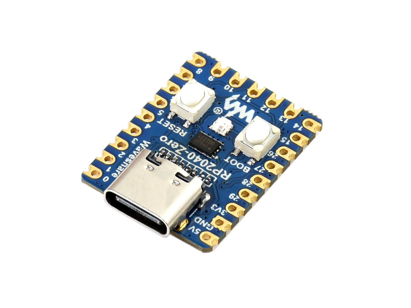
The RP2040-Zero’s onboard WS2812 LED is driven by GPIO16. It needs an addressable-LED driver rather than an ordinary GPIO high/low blink program. Start with the board’s supported LED example, then turn three colors into a small status interface.
02 / Materials & software
| Item | What to check |
|---|---|
| RP2040-Zero | Confirm the board model before using its GPIO assignment. |
| USB data cable | Use a reliable direct connection for development. |
| Compatible firmware | Select the documented MicroPython, CircuitPython, or C workflow. |
| Optional diffuser | Use only after the bare LED behaves correctly. |
03 / Connections & first setup
The first build uses the onboard LED and needs no external wiring. Do not configure GPIO16 for another purpose. If a future version adds an LED strip, treat its supply, logic compatibility, and current requirement as a separate hardware design.
04 / Build the project
- Run the LED baseline
Load the board-appropriate WS2812 example. Verify red, green, and blue individually at low brightness. This reveals color-order mismatches before status meanings are assigned.
- Write the state map
Choose three states such as available, busy, and attention. Give each a text name in the program as well as a color. Keep the definitions in one place so application code does not scatter raw color values.
- Add a local input
Start with serial commands typed from a computer. Accept only the documented commands and report an error for anything else. Display the current state in the serial console so it can be checked without relying on color.
- Handle disconnects
Decide what a lost host connection means. A timeout can return the indicator to a neutral state instead of displaying an old status forever. Keep the default after reset equally clear.
- Check real use
Look at the indicator in daytime and at night. Lower brightness before adding a diffuser. If several people will use it, add a printed legend rather than expecting everyone to infer the same meaning from color.
Serial command contract
AVAILABLE -> dim green
BUSY -> dim blue
ATTENTION -> dim amber
Unknown command -> keep state and report an error
05 / Check the result
| Check | Expected behavior |
|---|---|
| Primary colors | Driver color order matches the observed LED. |
| Unknown input | The program remains responsive. |
| Restart | The documented neutral state appears. |
Troubleshooting. A dark LED with a working board may mean the wrong driver, pin, or firmware target. Do not connect external voltage to the LED data pin. Test with the official example again before changing the status parser.
06 / Sources & build notes
Prepared by PineMux from the official sources above. These are editorial build instructions; this project has not been bench-tested by PineMux. The cover shows reference hardware or a source project; image credit is provided above. Use the manufacturer’s revision-specific diagrams for exact wiring.